Beware of programmers who carry screwdrivers! Or soldering irons. Experimenting with electronics is a hobby I rediscovered in the late 1990s. By far my most complex project was the design and construction of a 4-bit processor using low-level logic circuits. Although this machine has little practical utility, it serves as a useful educational tool due, in part, to its relative simplicity. Yet despite its simple design, the processor demonstrates many key concepts, including the use of microcode, a two-phase clock for controlling the processor's components, and even a primitive form of instruction pipelining.
The clock generator circuit of my 4-bit processor uses a series of simple logic components to generate a two-phase clock signal using a crystal resonator. The diagram below show the signal as it appears on an oscilloscope screen at various test points.

The following table summarizes the operational characteristics of my 4-bit experimental processor:
| Data bus | 4 bits |
| Address bus | 8 bits |
| Memory | 256 4-bit word |
| Accumulator | 8 bits |
| Program counter | 8 bits |
| Data address register (internal) | 8 bits |
| Instruction register (internal) | 4 bits |
| Flags | Carry, Zero, Data (external I/O) |
| Instruction set | 16 variable length instructions |
The 16 machine instructions are as follows:
| Opcode | Mnemonic | Size | Description |
| 0 | HLT | 1 | Halts the processor. Can be restarted manually by pressing a button. |
| 1 | LDA nn | 3 | Load 8-bit value from address nn into AC |
| 2 | STA nn | 3 | Store AC at address nn. |
| 3 | JMP nn | 3 | Continue execution at (i.e., set PC to) address nn. |
| 4 | SPC nn | 3 | Store current PC value at address nn. |
| 5 | AND nn | 3 | Compute logical AND of AC and nn, store result in AC. Set Z flag as appropriate. |
| 6 | OR nn | 3 | Compute logical OR of AC and nn, store result in AC. Set Z flag as appropriate. |
| 7 | ADD nn | 3 | Compute arithmetic sum of AC and nn, store result in AC. Set C and Z flags as appropriate. |
| 8 | SUB nn | 3 | Subtract nn from AC, store result in AC. Set C and Z flags as appropriate. |
| 9 | JNZ nn | 3 | Jump conditional; execute JMP nn if Z flag is not set. |
| A | CMP nn | 3 | Subtract nn from AC, discard result. Set C and Z flags as appropriate. |
| B | JND nn | 3 | Jump conditional; execute JMP nn if D flag is not set. |
| C | JNC nn | 3 | Jump conditional; execute JMP nn if C flag is not set. |
| D | ROL | 1 | Rotate AC left. Move C to least significant bit of AC. Move most significant bit to C. |
| E | ROR | 1 | Rotate AC right. Move C to most significant bit of AC. Move least significant bit to C. |
| F | CLF | 1 | Clear flags C, D, and Z. |
The LDA, STA, and SPC instructions are the only instructions that can read, or store, data at arbitrary memory locations. These instructions always operate on two 4-bit machine words at a time.
Other instructions use immediate arguments. That is, the instruction argument consists of two 4-bit words immediately following the single 4-bit instruction word.
This instruction set is obviously Spartan, but it is sufficient to implement any algorithm, memory size permitting. Restricting the instruction set to 16 instructions also greatly simplified design, since there's no need to fetch, and decode, instructions that consist of more than one 4-bit machine word.
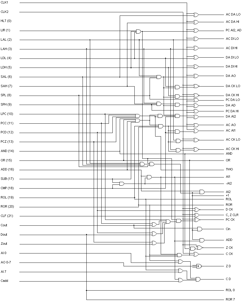
Due to the complexity of the Arithmetic Logic Unit, and the way it interacts with the processor's internal registers (accumulator, data address register, and program counter) I developed a wiring diagram that shows how the components of these are interconnected. Signal names on the left are those of the decoded microcode instructions, clock signals, and data/flag lines. Signal names on the right are those of various signals internal to the ALU and registers; the names should be self-explanatory. (E.g., DA AO is the name of the signal that enables, in the data address register, the 74LS244 that places the contents of this register on the address bus.) I also used these symbols when I labelled the chips (seen on the processor's photograph), to make the assembly process less error-prone.
The top half of the completed computer, as seen in the picture, contains the TTL logic chips that implement the above diagram, chips that comprise the Arithmetic Logic Unit, plus chips that make up the processor's accumulator, program counter, and data address register.
The bottom half of the computer contains the microcode ROM and microcode decoder, RAM, switches used to program the ROM and RAM, and the CPU clock. A 40-pin connector is used to connect the two halves via a short piece of ribbon cable.
The memory subsystem was the first component of my 4-bit processor that actually got built. Initially, my goal was less ambitious; I picked up some surplus 4×256 bit static RAM chips at a local electronics store, and I just wanted to see if I can build a simple circuit to store, and retrieve, data from these chips.
This didn't turn out to be a useless exercise, however. The DIP switches I used to exercise the memory chip are still used to load programs and data into my processor's memory. A planned modification to this circuit will also reuse the DIP switches and one of the LED displays to load, and display, I/O data which will allow my processor to interface with the outside world.
The memory subsystem interfaces with other components via the Data Bus and the Address Bus. The Data Bus is bidirectional; data can be both read and written. The Address Bus is unidirectional; addresses are generated by other processor components and are used by the memory subsystem to select the appropriate memory location for reading or writing.
In addition to the data and address buses, the memory subsystem also receives decoded instruction microcodes. These instruction microcodes control the operation of the subsystem. Specifically, nine instruction microcodes are recognized by this subsystem, decoded into one state and one trigger condition.
Microcodes LIR, LAL, LAH, LDL and LDH cause the subsystem to enter the MRD (Memory ReaD) state. In this state, the contents of memory appear on the Data Bus as output. The address from the Address Bus is used to select the desired memory location.
Microcodes SAL, SAH, SPL and SPH cause the subsystem to execute the MWR (Memory WRite) trigger. On the negative edge of CLK2, the memory subsystem fetches whatever data is on the Data Bus and stores it at the current address that is present on the Address Bus.
Finally, an additional signal (denoted PGM in the diagram below) indicates whether the processor is in its normal, operational state, or in the manual programming state. In the manual programming state, the memory contents can be read, and set, using the DIP switches that are part of the memory subsystem.

Perhaps the most interesting question with any processor is this: how do instruction codes (i.e., code words in memory) get turned into electrical signals that in turn trigger various events in the processor, altering its internal state?
There are many solutions to this problem, one of which is the use of microcode. While machine instructions are designed with the user in mind (well, inasmuch as machine language can be code user-friendly, that is!), microcode instructions represent internal state changes of the machine itself.
In the case of my 4-bit contraption, each machine code instruction is translated into several microcode instructions. Each microcode "instruction" is really just an electrical signal that, along with the clock signals activates various components of the processor. One of the tricks is the use of a two-phase clock, whose signals look like this:

As you can see, the first clock signal transitions from a high to a low state before the second clock signal. When the first clock signal is in a low state, subsystems in the processor respond by presenting information on their outputs, but without altering their internal states. When the second clock signal transitions from a high-state to a low state, subsystems respond by latching whatever data is present on their inputs and alter their internal state.
Designing the microcode set was only possible after I have developed the functional block diagram for the entire processor, and had more than a clue about the way its main components will work. The finalized microcode instruction set consists of 22 microcode instructions:
| Opcode | Instruction | Mnemonic | CLK1 (states) | CLK2 (triggers) |
| 00 | Halt | HLT | HLT | - |
| 01 | Load Instruction Register | LIR | APC+MRD+PCI+INC | LIR+LPC |
| 02 | Load AC low nybble from [DA]* | LAL | ADA+SDA+MRD+INC | LDL+LDA |
| 03 | Load AC high nybble from [DA] | LAH | ADA+MRD | LDH |
| 04 | Load DA low nybble from PC | LDL | APC+MRD+PCI+INC | LDL+LPC |
| 05 | Load DA high nybble from PC | LDH | APC+MRD+PCI+INC | LDH+LPC |
| 06 | Store AC low nybble to [DA]* | SAL | ADA+SAL+SDA+INC | MWR+LDA |
| 07 | Store AC high nybble to [DA] | SAH | ADA+SAH | MWR |
| 08 | Store PC low nybble to [DA] | SPL | ADA+SPL+SDA+INC | MWR+LDA |
| 09 | Store PC high nybble to [DA] | SPH | ADA+SPH | MWR |
| 0A | Load PC from DA | LPC | SDA+TWO | LPC |
| 0B | Load PC on No Carry | PCC | SDA+TWO | ~C->LPC |
| 0C | Load PC on No Data | PCD | SDA+TWO | ~D->LPC+CLD |
| 0D | Load PC on No Zero | PCZ | SDA+TWO | ~Z->LPC |
| 0E | Store AC&DA to AC | AND | SAC+SDA+AND | LAC+STF |
| 0F | Store AC|DA to AC | OR | SAC+SDA+OR | LAC+STF |
| 10 | Store AC+DA to AC | ADD | SAC+SDA+ADD | LAC+STF |
| 11 | Store AC-DA from AC | SUB | SAC+SDA+SUB | LAC+STF |
| 12 | Compute AC-DA | CMP | SAC+SDA+SUB | STF |
| 13 | Rotate Left | ROL | SAC+ROL | LAC+STF |
| 14 | Rotate Right | ROR | SAC+ROR | LAC+STF |
| 15 | Clear Flags | CLF | - | CLF |
*Use of square brackets implies indirection (e.g., store at [DA] means store in memory at the address in DA.)
The two rightmost columns tell us what happens in the various subsystems during the two clock phases. I called CLK1 events states (because they alter the output state of subsystems) and CLK2 events triggers (because they trigger an internal change upon the high-to-low transition of the clock signal.)
These states and triggers are essentially internally decoded electrical signals inside each subcomponent. They are described in detail along with the appropriate subcomponent's detailed description.
So now we can translate the 16 machine language instructions into microcode instructions:
| Opcode | Microcode |
| HLT | HLT,LIR |
| LDA | LDL,LDH,LAL,LAH,LIR |
| STA | LDL,LDH,SAL,SAH,LIR |
| JMP | LDL,LDH,LPC,LIR |
| SPC | LDL,LDH,SPL,SPH,LIR |
| AND | LDL,LDH,AND,LIR |
| OR | LDL,LDH,OR,LIR |
| ADD | LDL,LDH,ADD,LIR |
| SUB | LDL,LDH,SUB,LIR |
| CMP | LDL,LDH,CMP,LIR |
| JNZ | LDL,LDH,PCZ,LIR |
| JND | LDL,LDH,PCD,LIR |
| JNC | LDL,LDH,PCC,LIR |
| ROL | ROL,LIR |
| ROR | ROR,LIR |
| CLF | CLF,LIR |
So what does this all mean? Let's take, for instance, the LDA instruction. In plain English, this instruction accomplishes the following:
It is translated into five microcode instructions, which in turn cause the following to happen:
| Microcode | State/ Trigger |
Description |
| LDL | APC | PC places its current value on the address bus |
| PCI | PC places its current value on ALU's input | |
| MRD | Memory places its output at current address on data bus | |
| INC | ALU places input + 1 on its output | |
| LDL | DA fetches the contents of the data bus to its lower half | |
| LPC | PC fetches the ALU output | |
| LDH | APC | PC places its current value on the address bus |
| PCI | PC places its current value on ALU's input | |
| MRD | Memory places its output at current address on data bus | |
| INC | ALU places input + 1 on its output | |
| LDH | DA fetches the contents of the data bus to its upper half | |
| LPC | PC fetches the ALU output | |
| LAL | ADA | DA places its current value on the address bus |
| SDA | DA places its current value on ALU's input | |
| MRD | Memory places its output at current address on data bus | |
| INC | ALU places address bus + 1 on its output | |
| LDL | AC fetches the contents of the data bus to its lower half | |
| LDA | DA fetches the ALU output | |
| LAH | ADA | DA places its current value on the address bus |
| MRD | Memory places its output at current address on data bus | |
| LDH | AC fetches the contents of the data bus to its upper half | |
| LIR | APC | PC places its current value on the address bus |
| MRD | Memory places its output at current address on data bus | |
| INC | ALU places address bus + 1 on its output | |
| LIR | SEQ fetches instruction word from data bus and resets microcode counter | |
| LPC | PC fetches the ALU output |
The states and triggers are decoded by logic circuits inside the individual subsystems. As you can see, there's a lot of repetitiveness here, but that's precisely the point: the goal here is to reduce relatively complex instructions into simple, repetitive operations that can then be implemented in hardware.
The table below cross-references all 22 microcode instructions with states and triggers in each subsystem.
|
Microcode Instructions |
||||||||||||||||||||||
|
State/ |
HLT | LIR | LAL | LAH | LDL | LDH | SAL | SAH | SPL | SPH | LPC | PCC | PCD | PCZ | AND | OR | ADD | SUB | CMP | ROL | ROR | CLF |
|
Accumulator |
||||||||||||||||||||||
| LAC/LAC | X | X | X | X | X | X | ||||||||||||||||
| LAH/LAH | X | |||||||||||||||||||||
| LAL/LAL | X | |||||||||||||||||||||
| SAC/ | X | X | X | X | X | X | X | |||||||||||||||
| SAH/ | X | |||||||||||||||||||||
| SAL/ | X | |||||||||||||||||||||
|
Program Counter |
||||||||||||||||||||||
| APC/ | X | X | X | |||||||||||||||||||
| /LPC | X | X | X | X | C | D | Z | |||||||||||||||
| PCI/ | X | X | X | |||||||||||||||||||
| SPH/ | X | |||||||||||||||||||||
| SPL/ | X | |||||||||||||||||||||
|
Data Address |
||||||||||||||||||||||
| ADA/ | X | X | X | X | X | X | ||||||||||||||||
| DAI/ | ||||||||||||||||||||||
| LDA/LDA | X | X | X | |||||||||||||||||||
| LDH/LDH | X | |||||||||||||||||||||
| LDL/LDL | X | |||||||||||||||||||||
| SDA/ | X | X | X | X | X | X | X | X | X | X | X | X | ||||||||||
|
ALU |
||||||||||||||||||||||
| ADD/ | X | |||||||||||||||||||||
| AND/ | X | |||||||||||||||||||||
| /CLD | X | |||||||||||||||||||||
| /CLF | X | |||||||||||||||||||||
| CMP/ | ||||||||||||||||||||||
| OR / | X | |||||||||||||||||||||
| ROL/ | X | |||||||||||||||||||||
| ROR/ | X | |||||||||||||||||||||
| /STF | X | X | X | X | X | X | X | |||||||||||||||
| SUB/ | X | X | ||||||||||||||||||||
| TWO/ | X | X | X | X | ||||||||||||||||||
| INC/ | X | X | X | X | X | X | X | |||||||||||||||
| Sequencer | ||||||||||||||||||||||
| HLT/ | X | |||||||||||||||||||||
| /LIR | X | |||||||||||||||||||||
| Memory | ||||||||||||||||||||||
| MRD/ | X | X | X | X | X | |||||||||||||||||
| /MWR | X | X | X | X | ||||||||||||||||||
An interesting side note about this design is that despite its simplicity, it actually does some parallel execution, a feature of modern, high-speed processors. Take a look at the LDL microcode instruction, for instance. Loading the DA register from memory doesn't involve using the ALU, so it is possible to exercise the ALU in parallel, using it to increment the program counter.
But the microcode sequencer isn't responsible for executing microcode instructions (except, of course, for microcode instructions that affect the sequencer itself.) It is merely responsible for generating microcode instructions in the proper sequence from machine instructions. Microcode instructions are completely decoded; i.e., there are 22 individual control lines, one for each instruction.
Microcode is stored in a Flash ROM; an oversized Flash ROM in this case, but it so happens that that's what I had in my toolbox! It is a 28C16 Flash ROM from Microchip.
The sequencer circuit (shown below) also contains a series of DIP switches that are used to program the Flash ROM. These DIP switches are not strictly necessary; you can also use an external programmer. In my case, for one thing I didn't have an appropriate programmer unit handy when I was building this circuit, and I also found it convenient to program the chip in-circuit. Hence, the switches.
So, how does this thing work? Four-bit instruction codes are fetched from the data bus by a 74LS175 quad flip-flop. The instruction word is represents the upper 4 bits of the microcode address. The lower 4 bits are generated by a 74LS93 counter, leaving room for a maximum of 16 microcode words per instruction. The counter is controlled by the clock signals, the HLT and the LIR microcode instructions, and the START line (which is pulled low by a manually operated button).
The complete 8-bit microcode address is fed to the 28C16 via a 74LS244 octal buffer. The output of the 28C16 is then decoded into 22 individual lines using three 74LS138 3-to-8 demultiplexers. LEDs are also used to show the current state of the 22 control lines; I found this very helpful while testing/debugging the circuit.
Lastly, here's the actual microcode table, used to program the 28C16:
| Opcode | Address | Microcode words (binary) | Hex | Mnemonic |
| 0 HLT | (00) 00000000 | 00000 00001 00000 00000 00000 | 00 01 | HLT,LIR |
| 1 LDA | (10) 00010000 | 00100 00101 00010 00011 00001 | 04 05 02 03 01 | LDL,LDH,LAL,LAH,LIR |
| 2 STA | (20) 00100000 | 00100 00101 00110 00111 00001 | 04 05 06 07 01 | LDL,LDH,SAL,SAH,LIR |
| 3 JMP | (30) 00110000 | 00100 00101 01010 00001 00000 | 04 05 0A 01 | LDL,LDH,LPC,LIR |
| 4 SPC | (40) 01000000 | 00100 00101 01000 01001 00001 | 04 05 08 09 01 | LDL,LDH,SPL,SPH,LIR |
| 5 AND | (50) 01010000 | 00100 00101 01110 00001 00000 | 04 05 0E 01 | LDL,LDH,AND,LIR |
| 6 OR | (60) 01100000 | 00100 00101 01111 00001 00000 | 04 05 0F 01 | LDL,LDH,OR ,LIR |
| 7 ADD | (70) 01110000 | 00100 00101 10000 00001 00000 | 04 05 10 01 | LDL,LDH,ADD,LIR |
| 8 SUB | (80) 10000000 | 00100 00101 10000 00001 00000 | 04 05 11 01 | LDL,LDH,SUB,LIR |
| 9 JNZ | (90) 10010000 | 00100 00101 01101 00001 00000 | 04 05 0D 01 | LDL,LDH,PCZ,LIR |
| A CMP | (A0) 10100000 | 00100 00101 10010 00001 00000 | 04 05 12 01 | LDL,LDH,CMD,LIR |
| B JND | (B0) 10110000 | 00100 00101 01100 00001 00000 | 04 05 0C 01 | LDL,LDH,PCD,LIR |
| C JNC | (C0) 11000000 | 00100 00101 01011 00001 00000 | 04 05 0B 01 | LDL,LDH,PCC,LIR |
| D ROL | (D0) 11010000 | 10011 00001 00000 00000 00000 | 13 01 | ROL,LIR |
| E ROR | (E0) 11100000 | 10100 00001 00000 00000 00000 | 14 01 | ROR,LIR |
| F CLF | (F0) 11110000 | 10101 00001 00000 00000 00000 | 15 01 | CLF,LIR |
Only the bits shown here need to be programmed. Other bits are ignored. These include the top 3 bits of each microcode word, as well as unused words, such as the words at address 00010005 to 0001000F (the LDA instruction only uses five microcode words, at address 00010000-00010004.) This microcode table could also have been implemented as a diode ROM instead of wasting so much useful space in my 28C16; an address decode logic could have been used in conjunction with approx. 90 diodes.
The program counter of my 4-bit processor consists of a pair of 74LS175 circuits to hold 8 bits of data, plus several 74LS244 circuits to control input and output to and from this register. The decoder logic ensures that the program counter latches onto data, or emits data on the correct bus at the appropriate times during instruction cycles. In terms of its function, the program counter is very similar to the accumulator.

The data address register of my 4-bit processor consists of a pair of 74LS175 circuits to hold 8 bits of data, plus several 74LS244 circuits to control input and output to and from this register. The decoder logic ensures that the register latches onto data, or emits data on the correct bus at the appropriate times during instruction cycles. In terms of its function, this register is very similar to the accumulator.

The accumulator of my 4-bit processor consists of a pair of 74LS175 circuits to hold 8 bits of data, plus several 74LS244 circuits to control input and output to and from this register. The decoder logic ensures that the accumulator latches onto data, or emits data on the correct bus at the appropriate times during instruction cycles.

The arithmetic and logic unit, or ALU, is the most complex subsystem of this processor. Its purpose can be simply defined, however: depending on the current instruction microcode cycle, it is to take the data on one or both of its inputs, compute the desired result, and place the result on its output.
Components of the ALU perform computations in parallel. A selection logic decides which computation's output will appear on the ALU's output bus. Further selection logic is used to modify the results of computations; e.g., the difference between an addition and a subtraction is that during a subtraction, the two's complement of the second argument is computed before the two arguments are fed to the adder circuit.

The diagram at the bottom of this page provides an overview of my 4-bit contraption. You can also click on any of the subsystem rectangles to link directly to the respective page, or review some assembly instructions.
I began construction of this processor with its memory, by building a simple circuit to drive a 256×4 bit static RAM chip (2112) that I picked up at a local electronics store. At the time, it wasn't yet clear exactly where I was heading with this project; so I installed a set of microswitches to set the memory address and data, and two 7-segment LED displays to read my data switch settings and show the data at the current address in RAM.
Once I realized that this is going to be more than just a toy circuit to play with a RAM chip, the next step was to develop the operational concepts for my processor.
Once I had my instruction set, microcode instruction set, and register design, I was able to proceed with designing what really is the heart of the processor: a microcode instruction sequencer. This circuit turns instruction codewords into control signals that activate other processor components which in turn perform operations.
The simplest subsystems are the processor's internal registers: its accumulator, data address register, and program counter. Still, these are subsystems on their own right as they respond, and perform a variety of functions, in response to control signals.
Actual computations in this processor are done by its arithmetic and logic unit, or ALU. Most operations either use, or alter the contents of the processor's main internal register, its accumulator. Another internal register, the data address register, is used to facilitate access to memory for fetching, or writing, data words. The program counter register, on the other hand, is used to fetch instruction words; it is also incremented automatically as instructions are executed. Its contents can also be altered directly by conditional or unconditional jump instructions.
Not shown in the logic diagram, but vital to the operation of the computer, is its clock generator. The computer uses a two-phase clock. The idea is simple; on the first clock phase, internal states are preset in accordance with the current microcode instruction, and on the second phase, register values are fetched. For instance, if the current microcode instruction is to increment the program counter, the first clock phase configures the ALU to emit PC+1 on its output, while the second clock phase instructs the PC to fetch this new value from the ALU.
Finally, all the components of the processor are connected to each other via a variety of buses, some bidirectional, some unidirectional:
The memory address bus is an 8-bit bus that carries address information from the DA or PC to the memory module.
The memory data bus is a 4-bit bidirectional bus. It carries data from the AC or PC to memory; or, from memory to the AC or DA.
The instruction microcode bus carries the 22 microcode signals from the sequencer to all other system components.
The ALU communicates with other components via three 8-bit buses. Two input buses are used to send data to the ALU from the accumulator, DA, and PC. The ALU output is used to send results to the accumulator, DA, or PC.
Lastly, ALU flags (namely, the Carry, Data, and Zero flags) are sent from the ALU to the PC; the PC uses these flag results during the execution of conditional jump instructions.
| Bus |
Functional Unit |
|||||
| ACC | PC | SEQ | DA | MEM | ALU | |
| MA | - | W | - | W | R | - |
| MD | R/W | W | R | R | R/W | - |
| A1 | W | - | - | - | - | R |
| A2 | - | W | - | W | - | R |
| AO | R | R | - | R | - | W |
| AF | - | R | - | - | - | R/W |
| IM | R | R | R/W | R | R | R |